Test star tracker static, dynamic attitude efficiency, static accuracy, dynamic performance, polarity, and capture time inall-sky zone. The device is fixedly connected to the turntable, different angular speeds of the rotation can be set to realize the measurement of different sky areas.
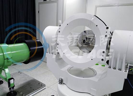
The dynamic accuracy test is to verify the dynamic performance of the device by testing the dynamic accuracy of the device under different angular velocitieson a high-precision turntable. The measurement of dynamic accuracy is the difference between the actual rotation angle of the turntable and the rotation angle of the equipment. A parallel light pipe is used to simulate a single starpoint, and the turntable is used for external synchronous transmission. The falling edge of the FEN signal of the device triggers the turntable. Theturntable outputs real-time position through RS422. The device image is saved in real-time by the image transmission software and the angle value is calculated. Internal exposure and line input compensation can verify the dynamic accuracy of the device.
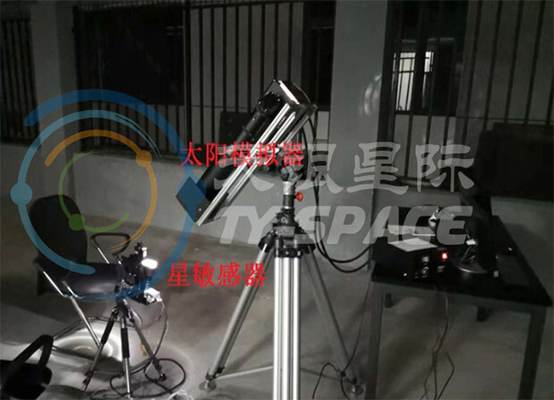
Test equipment stray light exclusion angle.Fix the device on the turntable, set different light intensity of the solar simulator according to the test requirements, adjust the angle of the device and the solar simulator, make the optical axis direction of the device lens coincides with the light path direction, record it as the zero degree position, adjust the rotation Record the working status of the equipment at different angles to verify the stray light suppression performance.
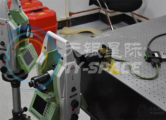
Measure the transformation matrix between the device sensor coordinate system and the satellite coordinate system, (the prism can be the reference prism that comes with the device sensor or the reference prism for the entire satellite). Utilizing the self-collimation function of the theodolite, the system alignment measurement is performed tocalibrate the device sensor prism coordinate system and the satellite coordinate system. It is used to measure the installation matrix between prisms, and equipment.
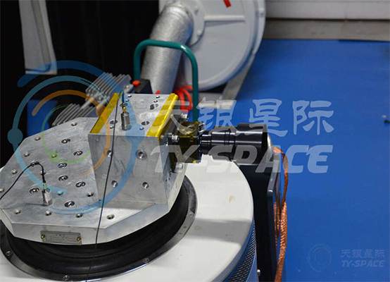
The frequency range of the electrical Shaker Tables is 5-3500Hz, the maximum no-load acceleration is 1000m / s2, and the maximum speed is 1.8m / s, the maximum displacement is 51mm, the maximum loadis 300kg, and the effective weight of the moving table is 6kg. Its working principle is the same as that of the loudspeaker, which is the current-carrying conductor is moved by the electromagnetic force in the magnetic field. When the current passing through the moving coil of the vibration table generates anexciting force with an alternating signal, a vibration movement occurs. The shaking table simulates the product vibration environment and is suitable for products working in a vibration environment such as national defense, aviation,and electronics. The tests include frequency sweep, sinusoidal vibration,random vibration, noise, and shock.
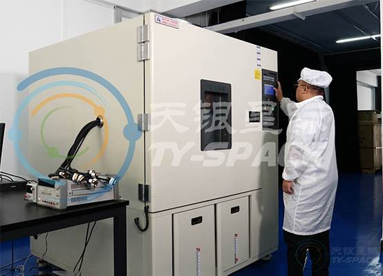
Programmable constant temperature and humidity test chamber temperature range is -60℃~+150℃, the volumeis 1000L. Constant temperature and humidity control system, PID control SSR, so that the heating and humidification of the system equals the amount of heat and humidity loss. The dry-wet bulb temperature measurement signal is compared with the A / D conversion input controller CPU and RAN and output to the I / Oboard. The I / O board sends instructions to make the air supply system and refrigeration system work and at the same time PID control SSR or heating SSR, or humidify SSR so that the amount of heat and humidity through the air supply system uniform test box to achieve a constant temperature and humidity. Applicable to the related industries such as optoelectronics, semiconductor industry, auto parts, household appliances, various electronic components and so on.
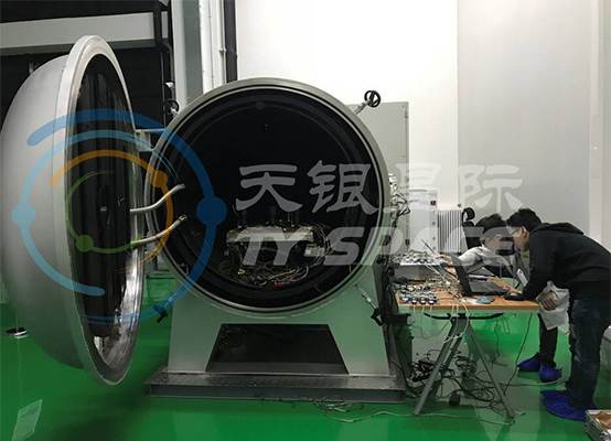
Vacuum degree can reach 5x10⁻⁵Pa, temperature range is -60℃~+120℃. During the simulation test, the test piece is in a working state, placed in the vacuum tank, and the gas in the container is extracted to the required value. The working parameters and environmental parameters of the test piece verify the adaptability of the test piece in a vacuum environment. The test is mostly used to inspect the manufacturing process of spacecraft equipmentand find that the spacecraft equipment fails early.
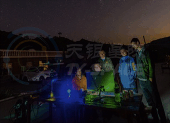
On February 19, 2019, the PST3S star tracker photographed on the ground and identified the photoelectric Morse code sent by the piaochong-1 satellite. The video shows that the star tracker attitude calculation can still work normally when the moon enters the field of view
TY-space star tracker successfully identified Hefeng-1 satellite debris in stargazing test
